Wednesday, November 25, 2015

Arduino Due based 3 phase sine wave generator


Hello Friends J
The purpose of this share is to help someone who's trying to utilize  Arduino due’s greater performance + lack of reference + non-helpful datasheet.
This project is able to generate up to 3 phase sine wave @ 256 samples / cycle at low freq (<1KHz) and 16 samples/cycle @ high freq (up to 20kHz), which is good enough to be smoothed by simple LPFs and the output is almost perfect.
The attached file was not my final version for I added some additional feature but the core is same to that. Note the samples/cycle was set lower than above statement.
Since the CPU capacity is maximized through the approach shown in the attached file, I used an Arduino Uno as control unit, who utilize Arduino Due's external interrupt to pass frequency value to Arduino Due. In addition to frequency control, the Arduino Uno also controls amplitude (through digital potential-meter + OpAmp) as well as I/O---there will be a lot of room to play with.

Step 1: Generate sine data array

Since real-time calculation is CPU demanding, a sine data array is required for better performance
uint32_t sin768 [] PROGMEM=....
while x= [0:5375]; y = 127+127*(sin (2*pi/5376/*or some # you prefer depends on requirement*/))

Step 2: Enabling parallel output

Unlike Arduino Uno, Due has limited reference. However in order to generate 3 phase sine wave based on Arduino Uno, 1st of all, performance is not applausable due to its low MCLK (16MHz while Due is 84MHz), 2nd, it's limited GPIO can produce max 2 phase output and you need additional analogue circuit to produce the 3rd phase (C=-A-B).
Following GPIO enabling was mostly based on try and trial+not helpful datasheet of SAM3X
PIOC->PIO_PER = 0xFFFFFFFE; //PIO controller PIO Enable register (refer to p656 of ATMEL SAM3X datasheet) and Arduino Due pin 33-41 and 44-51 were enabled
PIOC->PIO_OER = 0xFFFFFFFE; //PIO controller output enable register, refer to p657 of ATMEL SAM3X datasheet PIOC->PIO_OSR = 0xFFFFFFFE; //PIO controller output status register, refer to p658 of ATMEL SAM3X datasheet
PIOC->PIO_OWER = 0xFFFFFFFE; //PIO output write enable register, refer to p670 of ATMEL SAM3X datasheet
//PIOA->PIO_PDR = 0x30000000; //optional as insurance, does not seem to affect performance, digital pin 10 connect to both PC29 and PA28, digital pin 4 connect to both PC29 and PA28, here to disable PIOA #28 & 29

Step 3: Enabling interrupt

To maximize its performance, CPU load should be as low as possible. However due to the non-1to1 correspondence between the CPU pin and the Due pin, bit operation is necessary.
You can further optimize the algorithm but the room is very limited.
void TC7_Handler(void)
{ TC_Get Status(TC2,1);
t = t%samples; //use t%samples instead of 'if' to avoid overflow of t
PhaseAInc = (preset*t)%5376; //use %5376 to avoid array index overflow
PhaseBInc = (phaseAInc+1792)%5376;
PhaseCInc = (phaseAInc+3584)%5376;
p_A = sin768 [phaseAInc]<<1; //refer to PIOC: PC1 to PC8, corresponding Arduino Due pin: pin 33-40, hence shift left for 1 digit
p_B = sin768 [phaseBInc]<<12; //refer to PIOC: PC12 to PC19, corresponding Arduino Due pin: pin 51-44, hence shift left 12 digit
p_C = sin768 [phaseCInc]; //phase C output employee PIOC: PC21, PC22, PC23, PC24, PC25, PC26, PC28 and PC29, corresponding Arduino Due pin: digital pin: 9, 8, 7,6,5,4,3,10, respectively.
p_C2 = (p_C&B11000000)<<22; //this generates PC28 and PC29
p_C3 = (p_C&B00111111)<<21; //this generates PC21-PC26
p_C = p_C2|p_C3; //this generates parallel output of phase C
p_A = p_A|p_B|p_C; //32 bit output = phase A (8bit) |phase B|phase C
PIOC->PIO_ODSR = p_A; //output register =p_A
t++; }


Thanks and References

Hope you enjoyed this. If you have any suggestion, than I am here to listen you.
For any other help you can visit this site... https://www.robomart.com


Tuesday, November 24, 2015

Accelerometer Car with Arduino


This is kind of a side project my friend and I made based on Arduino micro-controller and MSP-430 micro-controller. And I would like to share the steps we took to come up with this accelerometer car.

Hope you like it J

Step 1: The Remote


For this you will need:

1. 
RF Tx and Rx
2. 
Accelerometer Module
3. 
Arduino UNO 
4. Jumper cables 
5. Arduino USB cables

I'm using an Encoder board along with the RF Tx i.e. the 
HT-12E board.

Connect the Accelerometer Module Pin
X------Analog Pin ------ A1
Y------Analog Pin ------ A2
All GNDS and VCC should be short separately.


We won’t need the z-axis as am trying to use the module to replicate the actions of a real driving style.
So if,
I bend the board Forward the car moves Forward.
I tilt it Left/ Right the car moves Left/Right.
I bend the board Backwards the car Stops.

So on those lines we have to first get the readings of the module for various triggering points so that we can move the car accordingly when a trigger point has been hit.
First run just the module on the Arduino and note the readings of the various tilt positions.


Make sure u place all the components on some sorta board so that your actions can be interpreted easily.

For me i got the trigger values for,
Forward----- x= xxx   y>= 400 
Stop---------- x= xxx   y<= 300
Left----------- x<= 300  y= xxx
Right--------- x>= 380  y= xxx

'xxx' means dont' care because those values doesn't trigger in the directions we are looking for.


Once you got all these info,Go on and connect the Accelerometer Module and the RF Tx to the Arduino to the pins given below

Accelerometer Module 
x--------- A1
y--------- A2

RF tx board
b0------- 7
b1------- 6
b2------- 5
b3------- 4

All GNDS and VCC should be short separately.

Place all the components on the same board.
You plug in the Arduino to the computer and dump the code on the Arduino.
(ACC-Rf-Tx code in the download file)

There you go, now you have the Remote READY.

NEXT STEP!!!!!

Step 2: The Car


For this u will need:

1. 
RF Tx and Rx
2. 
H-Bridge 
3. 
MSP-430
4. Jumper cables
5. 4 AA Battery holder x 1
6. AA Battery x 4
7. MSP-430 USB cable
8. 
Car along with DC motors and wheels

I'm using a Decoder board along with the RF Rx i.e. the 
HT-12D board. I'm using Energia IDE for the MSP-430.
First assemble the car with the wheels and dc motors i.e. if you don't already have a car lying around.
Then you will have to do the following connections.

RF Rx

b0 -------- 7
b1 -------- 8
b2 -------- 13
b3 -------- 14

H-Bridge

The two wires of each dc motor is given to the output of each input on the board 
and the input of the board is given to

taking A is for the right motor
inp A1 ------ 10
inp A2 ------ 9

taking B is for the left motor
inp B1 ------ 11
inp B2 ------ 12

The battery in connected to the h-bridge.
The enable pins of motor A and B are short to any Vcc pin.

P.S
The Gnd pins of all the boards involved are shorted separately and the Vcc pins of all the boards involved are shorted separately. 

Once you are done with the setup, connect the MSP-430 to the computer and dump the code on to it.
(Acc-RF-Rx code in the download file)

Make sure all the components are properly connected and attached on to the chassis of the car and nothing is falling off.

You now have the car ready.

NOW TEST IT!!!! 

Step 3: Thank You

Thank You for your patience and time for going through this instuctable.
Hope you liked it.

If you have any doubts or questions, mail them to me at,

shoeb20391@gmail.com


Here's the 
video of the working model =)

Ohh!!! I almost forgot, here are the code files.

Acc-test

Acc-Rf-Rx

Acc-Rf-Tx

If your car starts going in a different direction other than the prompted direction, then alter the codes and check the motor pins.


Waiting for your suggestion.


Monday, November 23, 2015

Configure Arduino Ohm Meter with LCD


This Instructable will show you how to design a Digital Ohm Meter using Arduino. This Ohm Meter is very precise...and totally DIY.


Step 1: Gather all the material.


Step 2: Connect the LCD to Arduino.


1) Connect the LCD to the breadboard as shown above (Please solder header pins first).
2)Make the connections as under:- 

* LCD RS pin to digital pin 12
* LCD Enable pin to digital pin 11
* LCD D4 pin to digital pin 5
* LCD D5 pin to digital pin 4
* LCD D6 pin to digital pin 3
* LCD D7 pin to digital pin 2
* LCD R/W pin to ground
* LCD VSS pin to ground
* LCD VCC pin to 5V
* A Potentiometer: * ends to +5V and ground * wiper to LCD VO pin (pin 3)

Step 3: Make the Voltage dividing circuit (main part)


This part is the most important part of this instructable. The Ohmmeter works on the principle of voltage dividing circuit. Which is given By:Vout = R1/R1+R2 * VinFrom here we can calculateR2which is given by:    
R2 = R1 * [1/ (Vin/Vout - 1)] Also we'll be using this formula in our Arduino Code. (See the code).
OK! So make the circuit very carefully... as shown above in the picture...
The TWO PROBES in the above picture are the two wires which we will connect to the object whose resistance we are measuring.

Step 4: Final Step!!


After all the connections your circuit would look somewhat like the picture above.....
1) Rotate the Knob of the pot according to your ease.
2) Use the LONGEST jumper wires to make the probes. They will provide you with more mobility and ease of movement.
3) If anyone of you doesn’t have the display, please inform me, i will post the code for Serial Monitor.
4) Connect the PROBES and Start Testing!!!!!!!!!.......
5) If you are facing any problem in this project...Please comment below....I'll be more than happy to help you.....
Thank you and PLEASE VOTE if you liked this instructable!!!!!!!!!!!!!!!!!!!!!!!!!!!!!!!


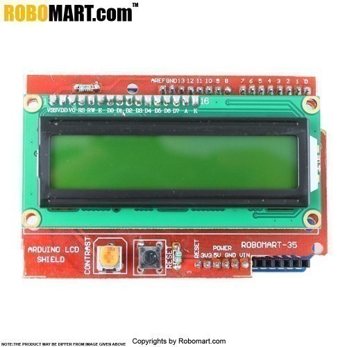
Arduino LCD Shield with Arduino Board


Here's an Arduino connected to a 2x16 HD44780 display, enclosed in 8"x4 1/2" Lexan. 

I used a modified version of the LCD Arduino library and hacked the LCD Smartie Sketch using Orbital Matrix commands. 


LCD Smartie is running the BigNum plug-ins. It shows Facebook news feeds, BBC Headlines, a Clock, local Weather and my folding at home status (team 144824) among other things.


This was a fun project, not too much soldering and had a high reward vs time invested. For more see my site
robomart.com

Enjoy. J

Saturday, November 21, 2015

Arduino UNO Fighter-Bot


This is a tutorial to build your own Fighter-boat using Arduino UNO. It can be either programmed over USB or Bluetooth. There is a reportandposterabout the project on share latex. Thegalleryis publicly available in Google+. The workshop slidescan be found on Google drive. All the source code, schematics files and documentation for the workshop are publicly available ongit-hub.       

Step 1: Circuit development


The circuit can be built according to the schematics here.

Step 2: Mechanical design


The frame can be milled using a CNC or cut by hand according to the schematics herethe servo motors must be modified to be continuous rotating according to guide here.

Step 3: Laser cutting chassis


The laser cutter design for the chassis can be found here. The idea of the laser cutter design is that the chassis can be easily assembled and disassembled.


Laser cutter mostly accept the SVG or/and DXF format(s). The difference between a laser cutter and CNC is that the laser cuts on the line, where the CNC cuts inside of the borders or outside. Which means the laser cutter design needs an extra margin, which is specific to the laser, mostly correlates with the power of the laser? The only good way to find out is to test :)

The cube here is designed for the margin testing purpose

Step 4: Programming


Connect the Bluetooth module to a 3.3V USB to serial 38400 baud and configure with the following:
·         AT
·         AT+RESET
·         AT+ORGL
·         AT+ROLE=0
·         AT+POLAR=1,0
·         AT+UART=57600,0,0
·         AT+INIT
·         AT+INQ
When using a Linux machine the Bluetooth can be configured with the following:
# Arduino Bluetooth device address and your Bluetooth
·         $ hcitool scan # to get arduino Bluetooth address
·         $ hciconfig -a | grep "BD Address" # to get your Bluetooth address
·         $ echo " 1234" > /var/lib/Bluetooth//pin-codes
·         $ rfcomm bind 0
More detail click here www.robomart.com/blog


Step 5: Testing


                                                                                                                                                                       Happy constructing xD